uPesy micro SD reader documentation
(Updated at 11/30/2022)
See also
If you have just received the uPesy µSD reader, I advise you to first look at the quick start guide if you haven’t already done so.
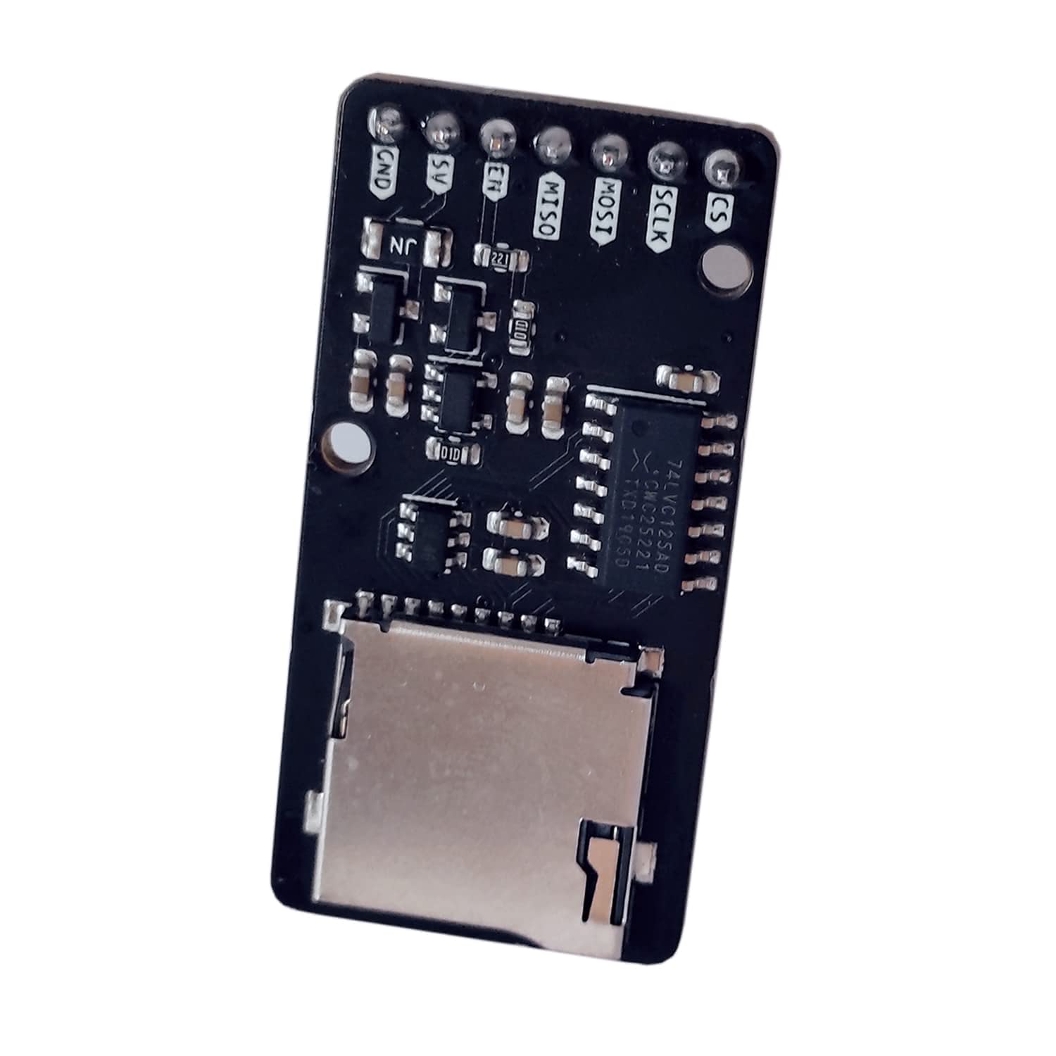
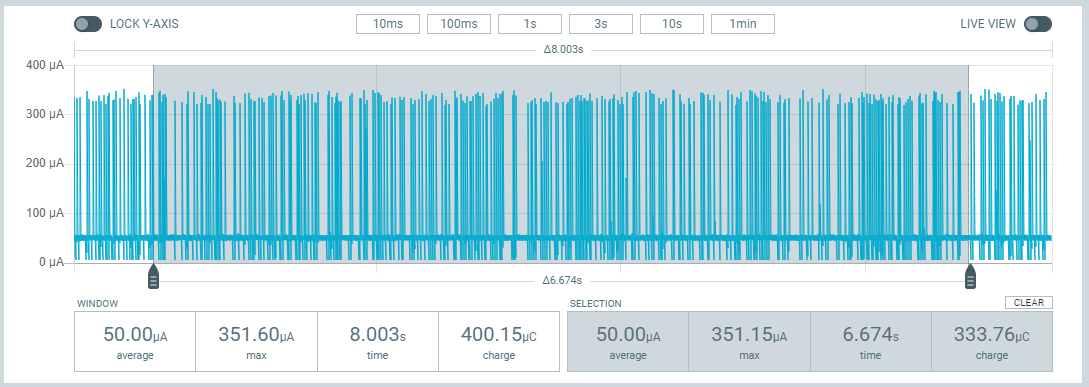
This micro SD card reader allows you to easily interface a microSD card with your favorite electronic board. It is compatible with all Arduino, ESP8266, ESP32, and Raspberry Pi Pico boards. Unlike other readers, it contains a power-saving mode that allows it to shut down entirely and thus consume only a few tens of µA. It is the ideal SD card reader to make a datalogger with batteries (a program that periodically records data on the SD card). It also has a protective battery to avoid damaging your micro SD board.

Technical specifications:
The communication with your board is done with the SPI protocol
The reader can be powered between 3.3V and 5V.
Note
To function correctly on an Arduino, it must be powered with 5V. For the boards working in 3.3V like the ESP32, even if it can be powered between 3.3V and 5V, the recommended voltage is 5V for optimal performance.
The reader contains a logic level converter (5V → 3.3V) to be used without worries by Arduino.
Contrary to the “low cost” modules, this reader contains several protections to protect your micro SD card
Short circuit protection with a 100 mA self-resetting thermal fuse
Electrostatic discharge (ESD) protection at the connector
Reverse polarity protection (if you reverse the +5V and the ground)
The reader contains two holes for M2 screws (Ø2,2 mm)
Current consumption :
Connection
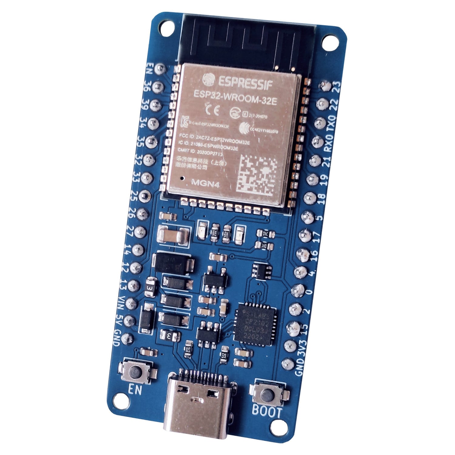
Here are the connections to make according to your board:
µSD Reader uPesy |
Arduino Uno | Nano |
ESP32 |
Pi Pico |
|---|---|---|---|
CS | SS |
D10 |
GPIO 5 |
GPIO 17 |
SCK | SCLK |
D13 |
GPIO 18 |
GPIO 18 |
MOSI |
D11 |
GPIO 23 |
GPIO 19 |
MISO |
D12 |
GPIO 19 |
GPIO 16 |
5V |
+5V |
+5V ou +3.3V |
+5V |
GND |
GND |
GND |
GND |
You will have noticed that the pin IN this is the pin that handles the power-saving mode. If this pin is not used, this mode is disabled by default: the module is usually powered. On the other hand, if a high logic state is imposed on this pin (5V or 3.3V depending on the microcontroller), the module will be in energy-saving mode: the micro SD board will be switched off.

