Save energy on the ESP32 with Deep Sleep
(Updated at 11/28/2022)
The ESP32 has different power-saving modes, which allow you to reduce power consumption by disabling some features. This is similar to putting a computer on standby to save power. Among these modes, the best known is Deep Sleep which put the ESP32 in a deep sleep state.
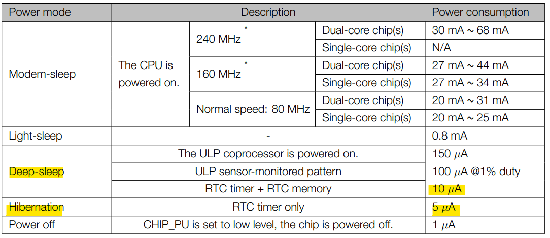
Consumption of the different modes of the ESP32, according to the datasheet
During this mode, the ESP32 can perform simple tasks and be woken up to operate normally.
Note
The keyword “Deep Sleep” is used a bit excessively to represent the most energy-saving mode of the ESP32, whereas it’s the “Hibernation” mode that consumes the least energy.
What is the Deep Sleep mode for?
This power-saving mode is useful when the ESP32 is battery-powered and the ESP32 “works” periodically. (For example, reading a value from a sensor and sending it through WiFi every 10 minutes). The battery will be discharged quickly if the ESP32 is 100% on 24 hours a day. With the Deep Sleep mode, the batteries will last much longer.
Deep Sleep mode puts the ESP32 in a rudimentary state. Indeed, in Deep Sleep mode, the 2 CPUs of the ESP32 do not work anymore, and it is the ULP (Ultra Low Processor) processor which takes over. This processor consumes very little power and can perform basic actions. The Flash and RAM are not powered anymore; only the RTC memory is still powered and can be used. WiFi and Bluetooth are, of course, also disabled.
Warning
The consumption of the ESP32 in this mode, in the µA range, will be slightly different depending on the tasks performed in this mode and the chosen wake-up source.
The wake-up sources of the ESP32 Deep Sleep mode
After putting the ESP32 in Deep Sleep mode, there are several ways to wake it up:
Use an internal timer to wake up the ESP32 at a selected time (internal wake-up)
Using capacitive touch sensors
Use the RTC pins
Note
We can combine different wake-up sources.
It is also possible to activate the Deep Sleep mode without configuring any wake-up sources. In this case, the ESP32 will be indefinitely in Deep Sleep mode until a manual reset is done by pressing the EN/RST button (or by reflashing the board). So you can’t block the ESP32 with the Deep Sleep mode.
For more information about the ESP32 Deep Sleep, I encourage you to consult the official documentation on this subject .
Put the ESP32 in Deep Sleep mode with Arduino code
When you want to use the Deep Sleep mode, you have to think about :
Configure the type of wake-up source of the ESP32: The consumption of the ESP32 in the µA range will be slightly different from the chosen wake-up source.
Optionally choose which peripherals you want to turn off or on during Deep Sleep mode, for example, which pins should remain on. By default, the ESP32 turns off all peripherals that are not needed to detect the wake-up trigger.
Use the function
esp_deep_sleep_start()to enter the Deep Sleep mode.
Warning
The measurements were created with the board uPesy ESP32 Low Power Devkit , a board optimized for very low power consumption when the ESP32 is in Deep Sleep. If you have a “generic” ESP32 board the power consumption will probably be much higher.
Note
The same uPesy ESP32 Low Power Devkit unit has been used to compare the consumption according to the wake-up sources. Indeed, the values vary from a few µA depending on the unit chosen.
Use a Timer as a wake-up source
This is how to wake up the ESP32 that consumes the least power. Only the RTC Timer is on. It is a counter that triggers an alarm (like an alarm clock) whose period is configurable.
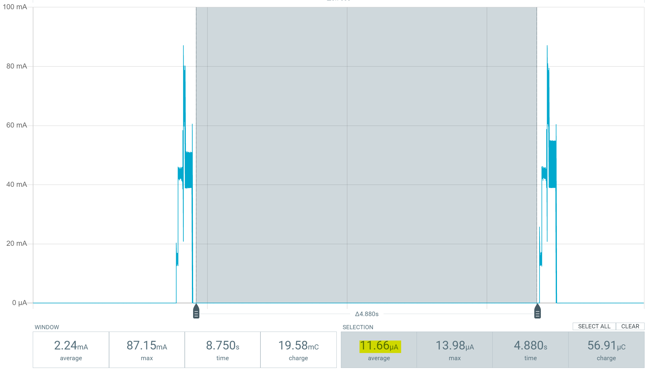
Here is an example code that wakes up the ESP32 every 5 seconds with a timer as the wake up source:
#define uS_TO_S_FACTOR 1000000
#define TIME_TO_SLEEP  5

RTC_DATA_ATTR int bootCount = 0;

void print_wakeup_reason(){
   esp_sleep_wakeup_cause_t wake_up_source;

   wake_up_source = esp_sleep_get_wakeup_cause();

   switch(wake_up_source){
      case ESP_SLEEP_WAKEUP_EXT0 : Serial.println("Wake-up from external signal with RTC_IO"); break;
      case ESP_SLEEP_WAKEUP_EXT1 : Serial.println("Wake-up from external signal with RTC_CNTL"); break;
      case ESP_SLEEP_WAKEUP_TIMER : Serial.println("Wake up caused by a timer"); break;
      case ESP_SLEEP_WAKEUP_TOUCHPAD : Serial.println("Wake up caused by a touchpad"); break;
      default : Serial.printf("Wake up not caused by Deep Sleep: %d\n",wake_up_source); break;
   }
}

void setup(){
   Serial.begin(115200);

   ++bootCount;
   Serial.println("----------------------");
   Serial.println(String(bootCount)+ "th Boot ");

   // Displays the reason for the wake up
   print_wakeup_reason();

   //Timer Configuration
   esp_sleep_enable_timer_wakeup(TIME_TO_SLEEP * uS_TO_S_FACTOR);
   Serial.println("ESP32 wake-up in " + String(TIME_TO_SLEEP) + " seconds");

   // Go in Deep Sleep mode
   Serial.println("Goes into Deep Sleep mode");
   Serial.println("----------------------");
   delay(100);
   esp_deep_sleep_start();
   Serial.println("This will never be displayed");
}

void loop(){
}
The function print_wakeup_reason() displays the ESP32 wake-up source. During the first ESP32 boot, the wake-up was not caused by the Deep Sleep but by the “Hard resetting via RTS pin…” on the Arduino IDE. Then during the next boots, the ESP32 is woken up from deep sleep thanks to a timer every 5 seconds.
You can change the Deep Sleep duration by modifying the timer with the function esp_sleep_enable_timer_wakeup() .
ets Jun 8 2016 00:22:57

rst: 0x10 (RTCWDT_RTC_RESET), boot: 0x13 (SPI_FAST_FLASH_BOOT)
configsip: 0, SPIWP: 0xee
clk_drv: 0x00, q_drv: 0x00, d_drv: 0x00, cs0_drv: 0x00, hd_drv: 0x00, wp_drv: 0x00
mode: DIO, clock div: 1
load: 0x3fff0018, len: 4
load: 0x3fff001c, len: 1216
ho 0 tail 12 room 4
load: 0x40078000, len: 9720
ho 0 tail 12 room 4
load: 0x40080400, len: 6352
entry 0x400806b8
----------------------
1th Boot
Wake up not caused by Deep Sleep: 0
ESP32 wake-up in in 5 seconds
Goes into Deep Sleep mode
----------------------
ets Jun 8 2016 00:22:57

rst: 0x5 (DEEPSLEEP_RESET), boot: 0x13 (SPI_FAST_FLASH_BOOT)
configsip: 0, SPIWP: 0xee
clk_drv: 0x00, q_drv: 0x00, d_drv: 0x00, cs0_drv: 0x00, hd_drv: 0x00, wp_drv: 0x00
mode: DIO, clock div: 1
load: 0x3fff0018, len: 4
load: 0x3fff001c, len: 1216
ho 0 tail 12 room 4
load: 0x40078000, len: 9720
ho 0 tail 12 room 4
load: 0x40080400, len: 6352
entry 0x400806b8
----------------------
2th Boot
Wake up caused by a timer
ESP32 wake-up in in 5 seconds
Goes into Deep Sleep mode
----------------------
Use a single GPIO pin as a wake-up source
We can also use a GPIO pin with a push button to wake up the Deep Sleep ESP32. This is typically what devices that wake up instantly when a button is pressed (phones, for example) do.
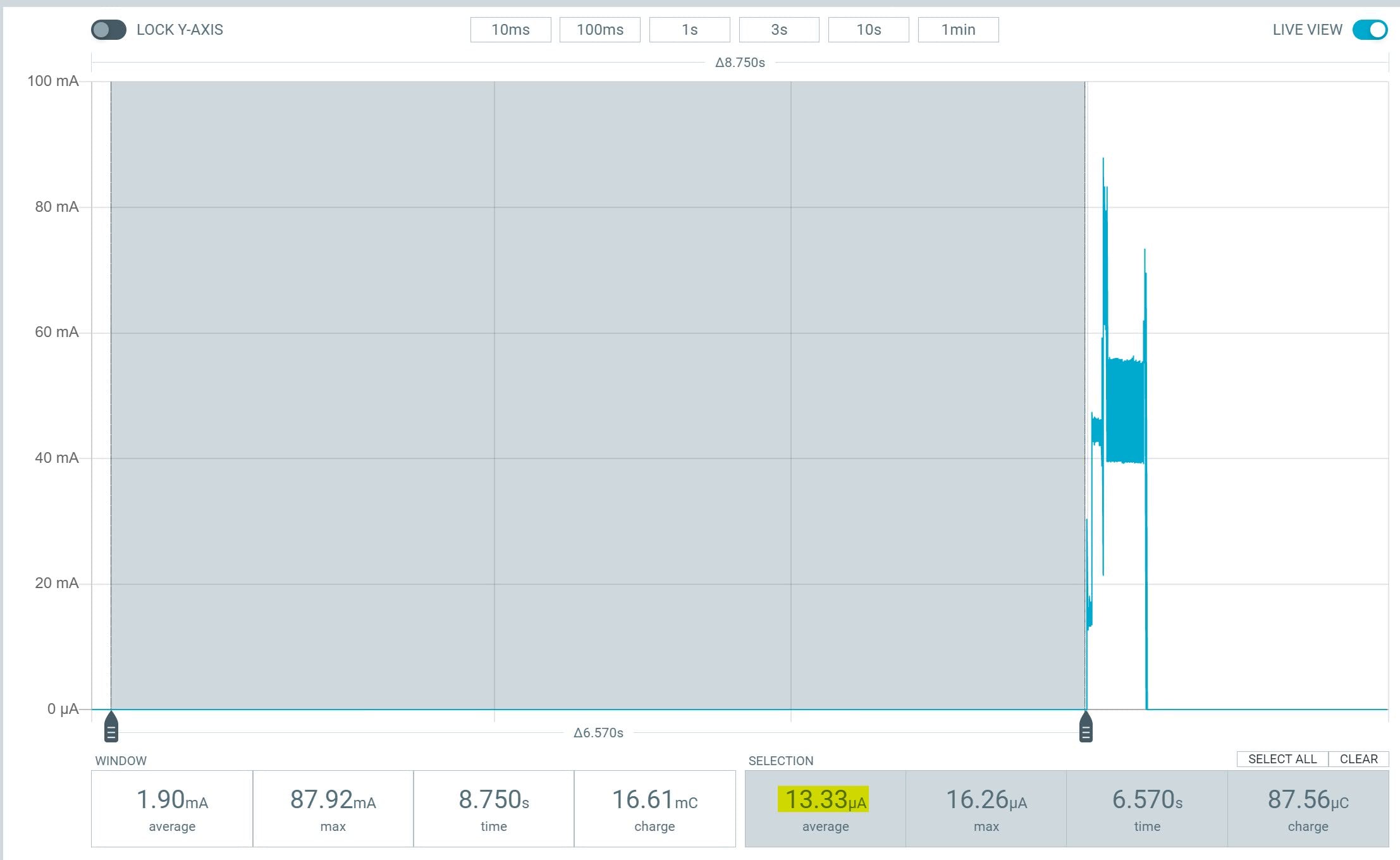
Power consumption of 13.5µA in deep-sleep mode powered by 4.2V
The peak corresponds to the consumption of the ESP32 when it wakes up. The consumption is slightly higher than with a timer.
Warning
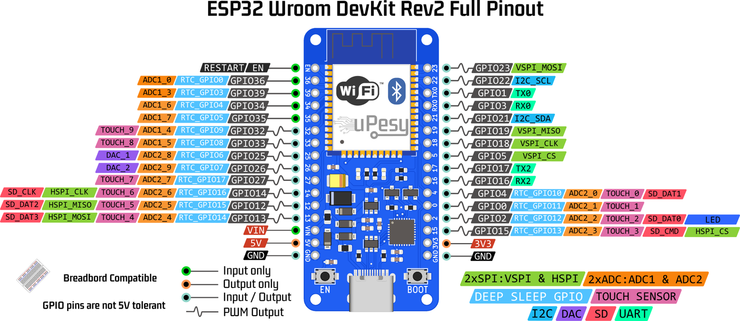
Only the RTC_GPIO pins can be used (light blue labels on the pinout below)
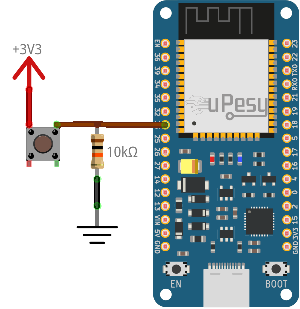
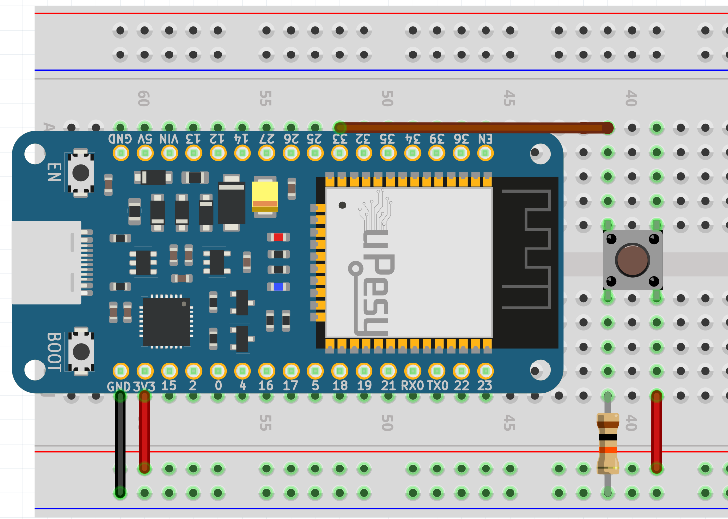
In this example, a push button with an external pulldown resistor connected to pin 33 is used:
RTC_DATA_ATTR int bootCount = 0;

void setup(){
   Serial.begin(115200);

    ++bootCount;
    Serial.println("----------------------");
    Serial.println(String(bootCount)+ "th Boot ");

    //Displays the wake-up source
    print_wakeup_reason();

    //Configure GPIO33 as a wake-up source when the voltage is 3.3V
    esp_sleep_enable_ext0_wakeup(GPIO_NUM_33,HIGH);

    //Rentre en mode Deep Sleep
    Serial.println("Goes into Deep Sleep mode");
    Serial.println("----------------------");
    esp_deep_sleep_start();
}

void loop(){}

void print_wakeup_reason(){
   esp_sleep_wakeup_cause_t wake_up_source;

   wake_up_source = esp_sleep_get_wakeup_cause();

   switch(wake_up_source){
      case ESP_SLEEP_WAKEUP_EXT0 : Serial.println("Wake-up from external signal with RTC_IO"); break;
      case ESP_SLEEP_WAKEUP_EXT1 : Serial.println("Wake-up from external signal with RTC_CNTL"); break;
      case ESP_SLEEP_WAKEUP_TIMER : Serial.println("Wake up caused by a timer"); break;
      case ESP_SLEEP_WAKEUP_TOUCHPAD : Serial.println("Wake up caused by a touchpad"); break;
      default : Serial.printf("Wake up not caused by Deep Sleep: %d\n",wake_up_source); break;
   }
}
An EXT0 interrupt is generated when the button is pressed and wakes up the ESP32
In the serial monitor, we obtain :
ets Jun 8 2016 00:22:57

rst: 0x10 (RTCWDT_RTC_RESET), boot: 0x13 (SPI_FAST_FLASH_BOOT)
configsip: 0, SPIWP: 0xee
clk_drv: 0x00, q_drv: 0x00, d_drv: 0x00, cs0_drv: 0x00, hd_drv: 0x00, wp_drv: 0x00
mode: DIO, clock div: 1
load: 0x3fff0018, len: 4
load: 0x3fff001c, len: 1216
ho 0 tail 12 room 4
load: 0x40078000, len: 9720
ho 0 tail 12 room 4
load: 0x40080400, len: 6352
entry 0x400806b8
----------------------
1th Boot
Wake up not caused by Deep Sleep: 0
Goes into Deep Sleep mode
----------------------
ets Jun 8 2016 00:22:57

rst: 0x5 (DEEPSLEEP_RESET), boot: 0x13 (SPI_FAST_FLASH_BOOT)
configsip: 0, SPIWP: 0xee
clk_drv: 0x00, q_drv: 0x00, d_drv: 0x00, cs0_drv: 0x00, hd_drv: 0x00, wp_drv: 0x00
mode: DIO, clock div: 1
load: 0x3fff0018, len: 4
load: 0x3fff001c, len: 1216
ho 0 tail 12 room 4
load: 0x40078000, len: 9720
ho 0 tail 12 room 4
load: 0x40080400, len: 6352
entry 0x400806b8
----------------------
2th Boot
Wake-up from external signal with RTC_IO
Goes into Deep Sleep mode
-----------------
Use several GPIO pins to wake up the ESP32
It is also possible to use several GPIO pins to trigger the wake-up of the ESP32 when certain conditions are met:
ESP_EXT1_WAKEUP_ANY_HIGH: ESP32 wakes up when all selected GPIO pins are lowESP_EXT1_WAKEUP_ALL_LOW: ESP32 wakes up when one of the selected GPIO pins is high
The power consumption is the same as with a single GPIO pin.
The configuration of this mode is a little more complicated because it is necessary to create a bitmask. We create a mask where the position of the bits of the mask corresponds to the numbers of the pins. Let’s suppose that we choose pins 27, 33 and 36, then we create a binary mask where the positions 27 , 33 and 36 will be 1 and the others 0 :
This section is available to premium members only. You still have 85% to discover.
Subscribe for only 5$/monthAlready subscribed? Sign in
Use a touchpad as a wake-up source
It is the most consuming wake-up source
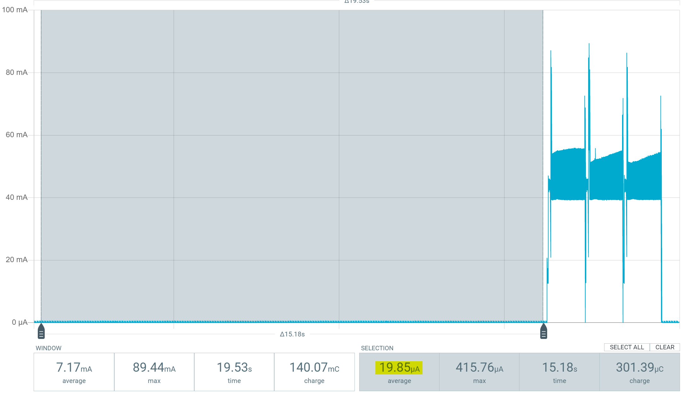
The ULP processor turns on 40 times per second to measure the capacitance of the capacitive sensor: this generates current peaks of about 400µA.
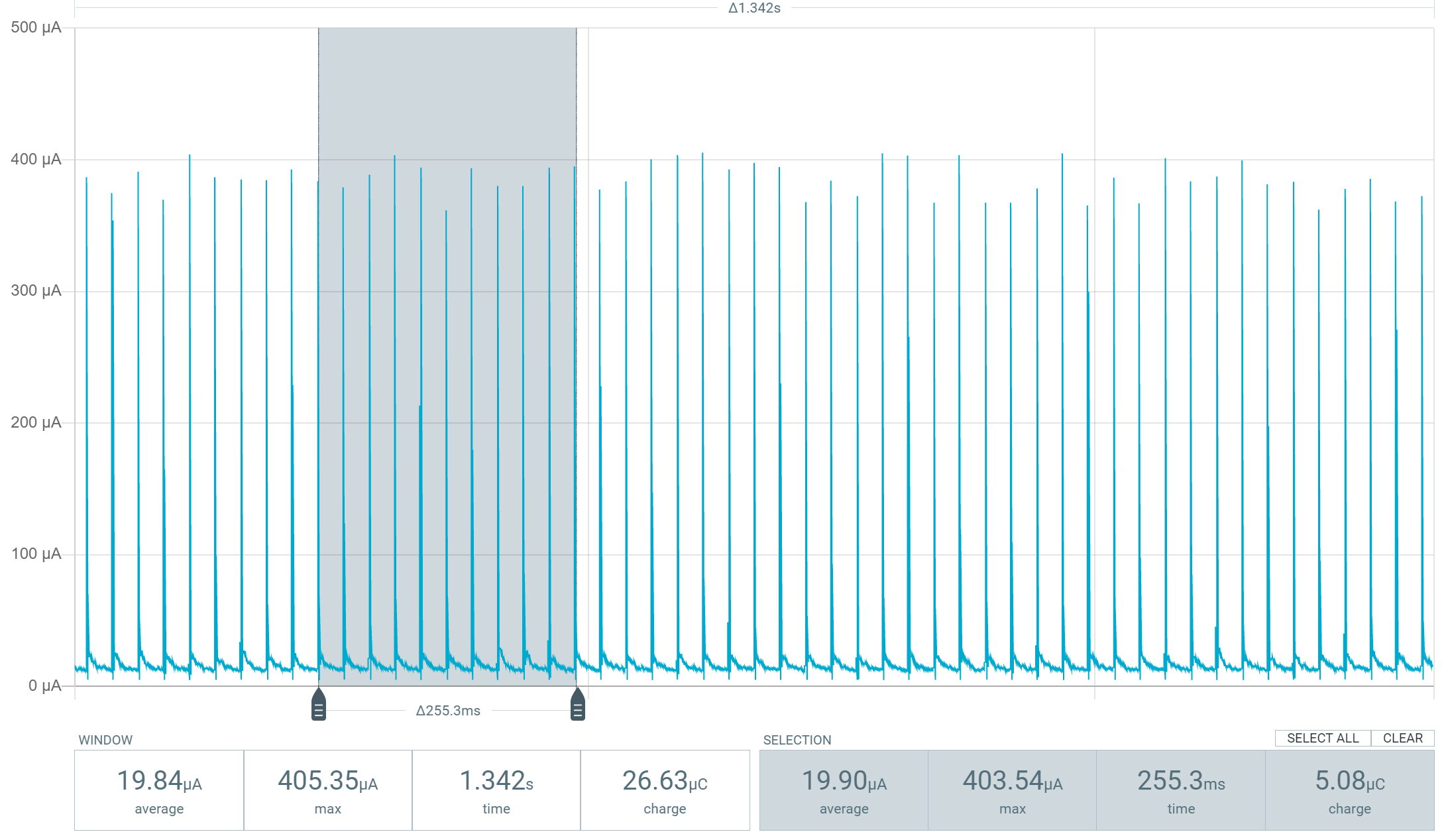
Zoom on the current peaks when measuring the touchpad with the ESP32 in Deep Sleep
The schematic consists of a single wire connected to the pin GPIO4 capacitive sensors, identical to the one proposed in the article that explains the operation of the capacitive sensors of the ESP32 . Here is the code used to wake up the ESP32 with the touchpads :
#define seuil 30 //Detection threshold for the capacitive sensor

RTC_DATA_ATTR int bootCount = 0;
touch_pad_t touchPin;

void fonction_isr(){
}

void setup(){
   Serial.begin(115200);

   ++bootCount;
   Serial.println("----------------------");
   Serial.println(String(bootCount)+ "th Boot ");

   //Displays the source of the wake-up call and the touchpad number
   print_wakeup_reason();
   print_wakeup_touchpad();

   //Configuration of an interrupt for the T0 touchpad (GPIO4)
   touchAttachInterrupt(T0, fonction_isr, seuil);

   //Activate wake up by touchpads
   esp_sleep_enable_touchpad_wakeup();

   //Goes into Deep Sleep mode
   Serial.println("Goes into Deep Sleep mode");
   Serial.println("----------------------");
   esp_deep_sleep_start();
}

void loop(){
}

void print_wakeup_reason(){
   esp_sleep_wakeup_cause_t wake_up_source;

   wake_up_source = esp_sleep_get_wakeup_cause();

   switch(wake_up_source){
      case ESP_SLEEP_WAKEUP_EXT0 : Serial.println("Wake-up from external signal with RTC_IO"); break;
      case ESP_SLEEP_WAKEUP_EXT1 : Serial.println("Wake-up from external signal with RTC_CNTL"); break;
      case ESP_SLEEP_WAKEUP_TIMER : Serial.println("Wake up caused by a timer"); break;
      case ESP_SLEEP_WAKEUP_TOUCHPAD : Serial.println("Wake up caused by a touchpad"); break;
      default : Serial.printf("Wake up not caused by Deep Sleep: %d\n",wake_up_source); break;
   }
}

void print_wakeup_touchpad(){
   touch_pad_t pin;
   touchPin = esp_sleep_get_touchpad_wakeup_status();
   switch(touchPin){
      case 0  : Serial.println("Wire touched at GPIO 4"); break;
      case 1  : Serial.println("Wire touched at GPIO 0"); break;
      case 2  : Serial.println("Wire touched at GPIO 2"); break;
      case 3  : Serial.println("Wire touched at GPIO 15"); break;
      case 4  : Serial.println("Wire touched at GPIO 13"); break;
      case 5  : Serial.println("Wire touched at GPIO 12"); break;
      case 6  : Serial.println("Wire touched at GPIO 14"); break;
      case 7  : Serial.println("Wire touched at GPIO 27"); break;
      case 8  : Serial.println("Wire touched at GPIO 33"); break;
      case 9  : Serial.println("Wire touched at GPIO 32"); break;
      default : Serial.println("Wake up not caused the touchpads"); break;
   }
}
Erasing RAM: how to keep data in Deep Sleep
When the Deep Sleep mode is activated, the CPU and the RAM are not powered anymore. This means that when the ESP32 wakes up from Deep Sleep, all the variables contained in the RAM are erased. Fortunately, an 8 KB RTC RAM remains on during Deep Sleep. To store variables in this memory, you must add the attribute RTC_DATA_ATTR .
For example, the variable that stores the number of ESP32 restarts in the example is stored in this memory.
RTC_DATA_ATTR int bootCount = 0;
Optimize consumption in Deep Sleep as much as possible
Since we are talking about saving current to the nearest µA, every detail counts. Even if it is impossible in practice to have the consumption indicated in the datasheet, because the measurements indicated are ideal and especially because the ESP32 is not the only component on the board that consumes energy, you can still save a few µA depending on your project.
Moreover, at this stage, it is more relevant to use the ESP-IDF framework directly in C (no Arduino or MicroPython code) to be able to modify the configuration of the ESP32 via the menuconfig file, which generates the sdkconfig.h
This section is available to premium members only. You still have 88% to discover.
Subscribe for only 5$/monthAlready subscribed? Sign in
