
How do microcontroller timers work?
(Updated at 02/02/2023)
You have probably heard of a timer, but do you really know what it is used for and how it works? In this article, we will discover the different use cases of a timer on a microcontroller as well as its theoretical operation. This knowledge will allow you to use timers in your Arduino, and MicroPython programs effectively. Let’s start by defining what a timer is. 😊
The Timer, an electronic counter
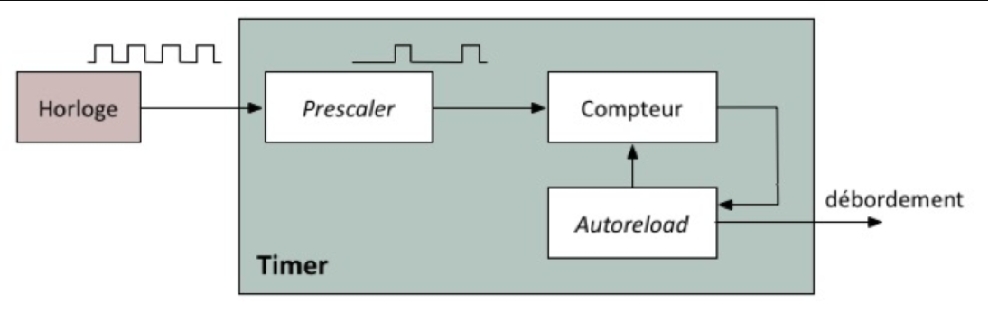
A timer is an electronic counter capable of counting time very accurately. It is a register inside a microcontroller that is incremented each time it receives a pulse from a clock signal generated internally by the microcontroller. We will use timers instead of the microprocessor to count, which is what the Arduino function delay() does.
The hardware timers are independent blocks of the CPU. They take care of counting continuously while the program can perform other functions.
Note
The Arduino functions millis() and micros() functions use a timer to work.
Timers provide additional functionality, such as triggering alarms when a certain threshold is reached. For example, tasks can be executed periodically with interrupts generated by a timer.
What is the purpose of having a timer on a microcontroller? - Use cases
The timer can be used for its basic function: to measure time accurately. It may be interesting to know how long a program has been running or how much time has elapsed since the program started.
In practice, we often use a unique feature of timers: generating interrupts when the counter reaches a certain threshold. Here is what you can do using this feature:
Scheduled tasks: a timer can be configured to trigger an interruption at regular intervals, which can be used to update displays, monitor sensor inputs, etc.
Generate PWM signals: a timer can be used to generate PWM signals to control the speed of a motor, the brightness of an LED, etc.
Event synchronization: a timer can synchronize events internally or with external devices.
Create timeouts: maximum time to wait
Note
Timers are used in Arduino functions without necessarily being aware of it, in basic functions (millis() and micros() ), for PWM and in libraries (Servo )
I will tell you more about the inner workings of a timer. It’s important to understand how it works under the hood to configure it correctly later in your programs. 😊
The internal workings of a timer
Timers cannot count indefinitely. They are limited by their resolution, which is measured in bits. For example, the Arduino has 2 timers of 8 bits and 1 of 16 bits. This means that 2 timers can count between 0 and 255 and the other between 0 and 65 535. On an ESP32 board, there are 4 timers of 64bits, which can count between 0 and 18,446,744,073,709,552,000 (there’s a lot to do 😉.)
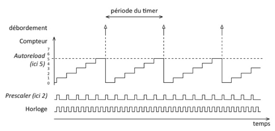
If the timer exceeds its maximum value, it will overflow. In this case, the counter is usually reset to zero by the <span style=’color:gray’>``autoreload`` </span><span style=’color:gray’>,</span> and an internal alarm is generated to warn the microprocessor.
The time that elapses between each “tick” of the timer obviously depends on the frequency of the clock. On each rising edge of the clock, the counter is incremented. At frequencies of the order of tens of MHz, the time is very short and the counter overflows very quickly.
Fortunately, it is possible to reduce this frequency thanks to internal components of the microcontroller, called dividers or prescalers in English. A**prescaler** allows the frequency of the clock to be divided and incremented more slowly. For example, with a prescaler of 4, the counter will count 4 times slower than the clock signal.
Note
A timer is configured with its period via the value of the prescaler and the autoreload .
Calculate the value of the prescaler and the autoreload from the desired timer period
The timer period is the time that elapses between 2 counter overflows. To calculate it, we can use the following formula:
Note
The counter counts from 0 to autoreload inclusive, i.e \((autoreload+1)\) values.
In general, we know the period of the timer we want: we look for the values of the parameters. There are several pairs of possible solutions for a given period. You can have a low prescaler (high count rate) with a high overflow or vice versa. We cannot find the 2 values separately. You have to choose one to find the other.
Let’s take an 80 MHz clock, and we want a timer period of 1 second. By choosing a prescaler of 1, the overflow value is :
The autoreload value must be storable in the timer register, i.e., have a value less than \(2^{résolution\space timers}\) bits. This is ok for the ESP32 but not for the Arduino timers. It would be necessary to use a more significant value for the prescaler.
Note
Sometimes it is not possible to find the exact values of the parameters. It will therefore be necessary to make approximations. We can minimize this effect by using the smallest possible prescaler.
If we want to get a value on 16bits for an Arduino timer, we can use a prescaler of 8000 and an autoreload of 9999:
Of course, other prescaler values are possible! The prescaler value is usually chosen arbitrarily, as large as possible, and then the threshold value is derived.
In practice, we use a value that simplifies the calculations: for example, a prescaler of 80 for the ESP32 permanent to configure the period of the timer to the nearest microsecond (the frequency of the clock is 80 MHz).
Simple, right? 😊
Note that the ESP32 hides the subtraction in the function code, so we can simplify by prescaling to 80: