
Control electrical devices with a Relay and a Pi Pico with Arduino code
(Updated at 01/20/2023)
The relay is a must-have for controlling appliances if you’re starting with home automation. The latest Raspberry Pi Pico W comes with a Wi-Fi module.
Warning
Working with line voltages is highly hazardous. Exercise great care if you must handle them. For permanent use, go for professional-grade relay modules and get your setup evaluated by an expert.
Getting started with a Relay
Relays are extremely simple to operate, even more so when sold as a pre-assembled circuit module.
Note
Select a module that includes a relay along with its circuitry rather than just the relay—building the logic part of the circuit yourself is not advised, as the relay cannot be placed on a breadboard and should not be for safety reasons.
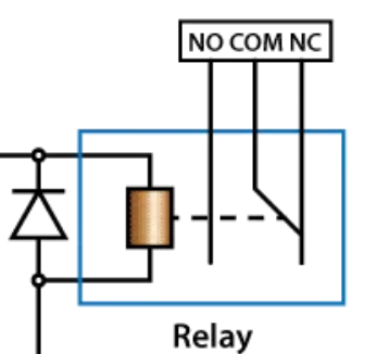
Presentation and functioning of a Relay
If you have never used a relay before or if you want to understand how it works, its use cases and its limits, In that case, I’d strongly suggest looking at this theoretical article on relay functioning .
A relay is a mechanical switch that can be used with a Raspberry Pi Pico to control an electrical circuit. It can be attached to devices that use DC power, like RGB LED strips and pumps, and to items that run on 220V mains electricity, such as fans, lights, heaters, and motors.
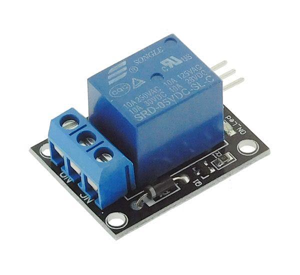
Connection of the SRD-05VDC-SL-C Relay
Arduino kits typically have the Songle manufacturer’s SRD-05VDC-SL-C relay. These modules come in two varieties: one with a single relay and another with multiple relays. Opting for the module with multiple channels is beneficial if you require independent control of multiple power circuits.
Note
This relay is designed to be powered by 5V (or 3.3V for the SRD- model 03VDC- SL-C).
Warning
Contrary to a schematic with a transistor, it’s essential to understand that the ground of the logic part and power parts’ ground should never be connected, especially with 220V AC or when there is no ground!
Relay Module |
Raspberry Pi Pico |
|---|---|
|
|
|
|
|
|
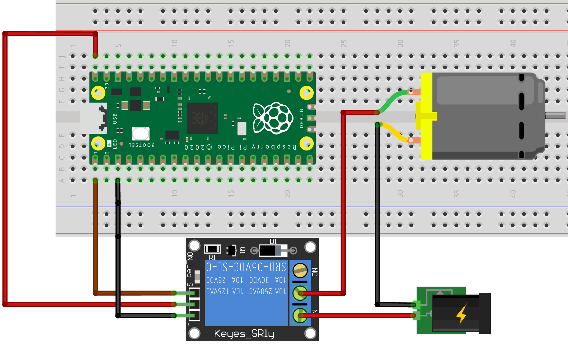
On the model SRD-05VDC-SL-C, there are three pins to drive the relay:
The pin
Son the left must be connected to a pin of the Pi Pico (hereGP0). It allows sending a signal to drive the relay.The middle pin is the power supply that must be connected to the
5Vof the Pi Pico (or3V3for SRD- model 03VDC- SL-C).The last pin, represented by
-, is the ground, which must be connected to a pinGND.
The relay has a 3-pin terminal block on the power side:
NC→ Normally Closed contact.COM→ the middle pin is called Common (COM).NO→ Normally Open contact.
Depending on your needs, the device must be attached to the COM terminal and either the NO or NC terminal on the relay. If you select the NO terminal, the circuit will be open by default, meaning no electrical current will flow. The current will only pass through the circuit if a signal is sent to the relay.
The circuit will be closed by default if the terminals COM and NC are chosen (unless the relay is activated). This means that the connected device will be turned on. But when the relay is activated, the circuit will open, and the device will no longer receive power.
It is wise to select the safest option if something fails to avoid accidents. For example, if powering a heating resistor with a device, a circuit should be chosen that will open if the relay fails (when the relay is out of service). This can help to protect against a potential fire.
Note
I recommend you to use COM and NO if the purpose is to switch on a device (lamp, motor, pump).
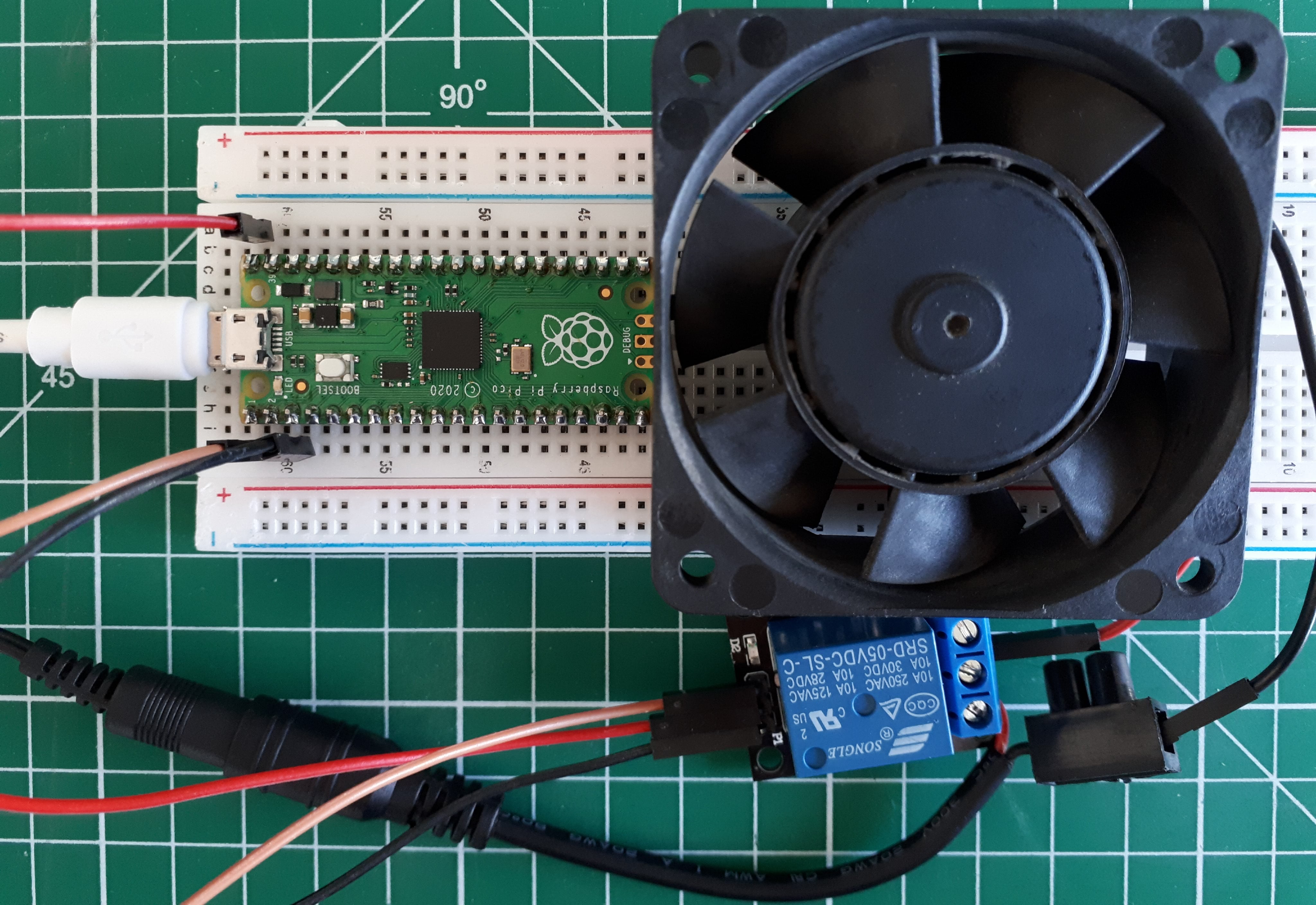
Here is an example of using a relay to power a computer fan:
Control the Relay with Arduino code on the Pi Pico
The Arduino code is relatively basic for now. It works like turning on and off an LED, the same as the famous blink sketch. You won’t need to get any extra libraries.
#define RELAIS 0

void setup() {
  pinMode(RELAIS,OUTPUT);
}

void loop() {
  digitalWrite(RELAIS, HIGH); // Le circuit est fermé pendant 200ms
  delay(200);
  digitalWrite(RELAIS,LOW); // Le circuit est ouvert pendant 5s
  delay(5000);
}
Note
The relay is controlled in all or nothing (0V or 5V) and not with a PWM signal with adjustable voltage.
And here is what it gives with the proposed circuit:
Note
A transistor circuit may be a better option when frequently turning a motor on and off.
Multi-channel advanced relay modules
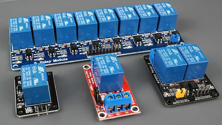
Relay modules with 1-8 channels are available. Each channel can control an output independently. They typically come with the same blue SRD-05VDC-SL-C relay.
Separate the Pi Pico from the Relay with Optocouplers
There is usually a built-in optocoupler on models with more than two channels to completely isolate the relay from your Pico.
Note
An optocoupler is a device completely separates a logic signal using a light signal with a transmitter and receiver for conversion.
This section is available to premium members only. You still have 77% to discover.
Subscribe for only 5$/monthAlready subscribed? Sign in