
Using a rotary encoder on a Raspberry Pi Pico in Arduino code
(Updated at 02/02/2023)
An encoder is a type of sensor used to determine the position and direction of rotation. It is often used in motors for servo control and user interfaces to replace potentiometers. In addition, many DIY modules come with an integrated pushbutton!
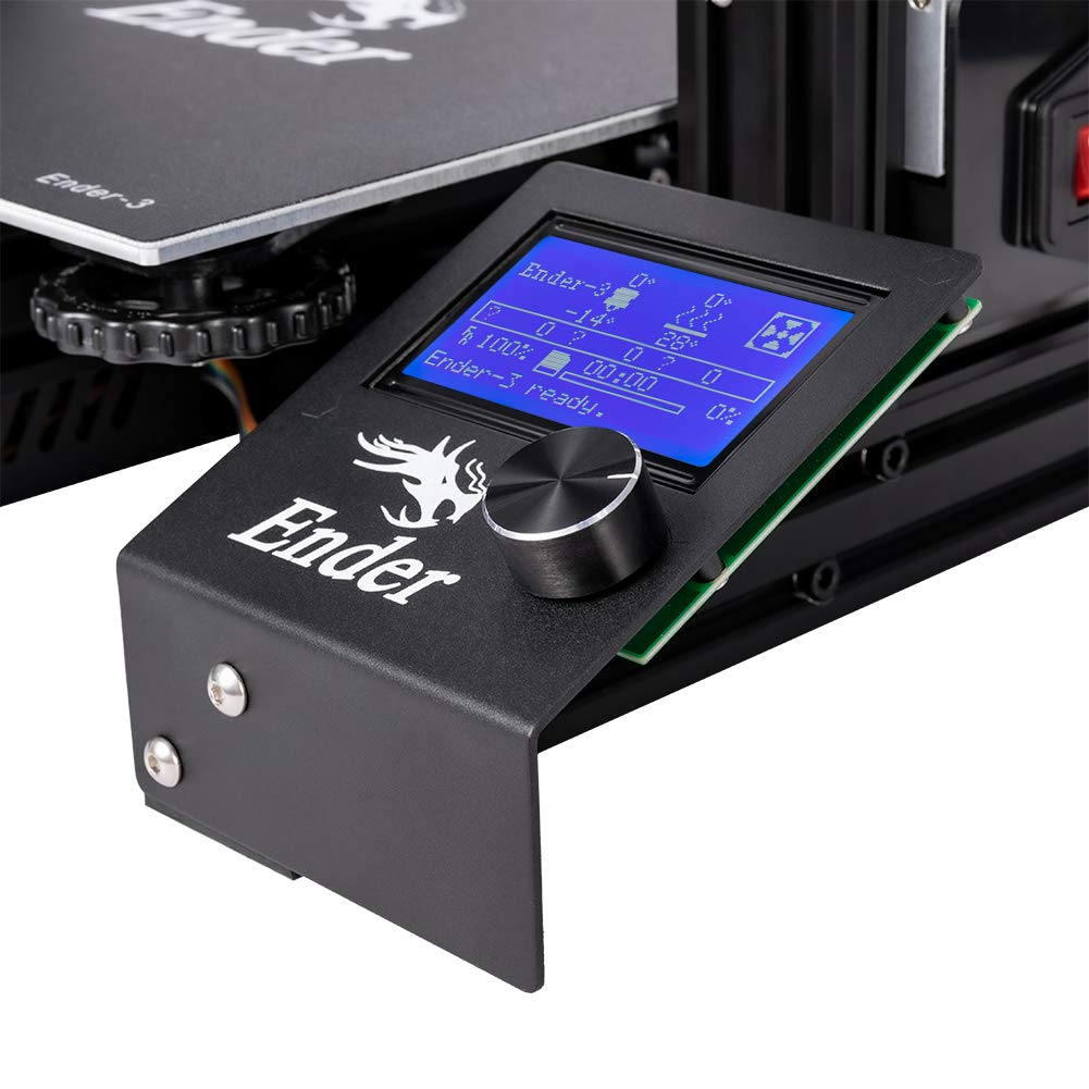
The control button on 3D printers is usually a rotary encoder
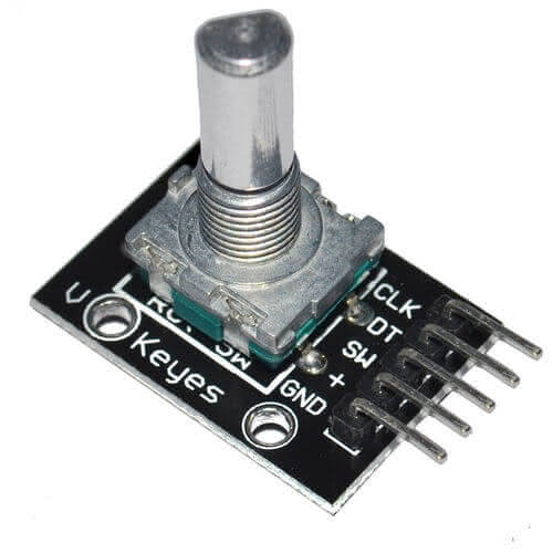
Handling a rotary encoder: the KY-040
This guide will show you how to use the <span style=’color:gray’>``KY-040`` </span> encoder module, often included in DIY kits, to create a user interface with our program. This can be used for various applications, such as selecting a menu or setting a variable.
Difference between rotary encoder and potentiometer
At first glance, the <span style=’color:gray’>``KY-040`` </span> may look like a potentiometer. However, there is a significant difference between the two. A potentiometer is an analog sensor that changes the value of a resistor. On the other hand, an encoder is a digital device with no limit on the number of revolutions it can make. It can rotate infinitely.
The encoder differs from a potentiometer in that it takes a certain number of “steps” with each revolution and sends a signal at each step. This difference can be felt in the movement of the knob: the potentiometer turns smoothly and continuously, whereas the encoder has a jerky, “stepped” feel.
An encoder can be connected to a microcontroller and send digital signals. Its accuracy depends on the number of steps per revolution. In comparison, the accuracy of a potentiometer relies on the accuracy of the analog-to-digital converter (ADC) used to calculate its position.
Note
A potentiometer is an adjustable resistor used to change analog parameters such as the volume of an amplifier. On the other hand, an encoder is responsible for accurately indicating angular position and direction.
Theoretical operation of a rotary encoder
This document doesn’t go into the technical aspects of encoders. However, if you want to learn more about the physical operation, the different technologies and the classical topologies (e.g., to understand how an optical quadrature phase encoder works 😨), please consult the theoretical presentation of a rotary encoder .
Connections of the KY-040 rotary encoder to the Pi Pico
This rotary encoder has 2 signals to know the position: CLK and DT . The pin SW pin is connected to the integrated push button (SWitch).
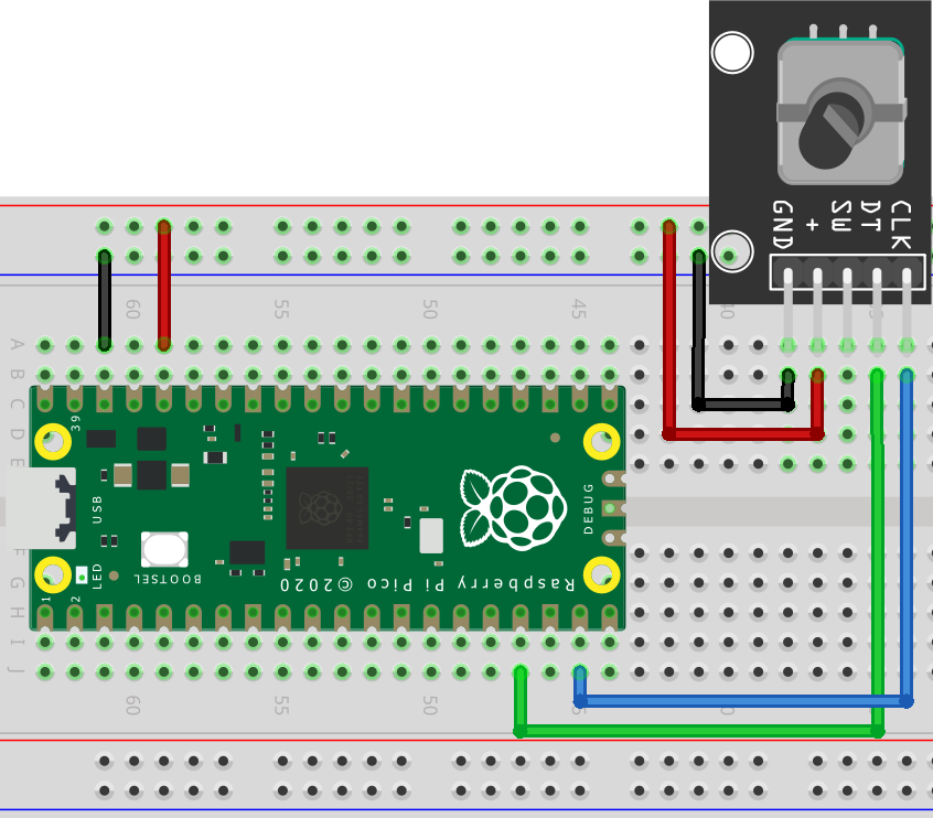
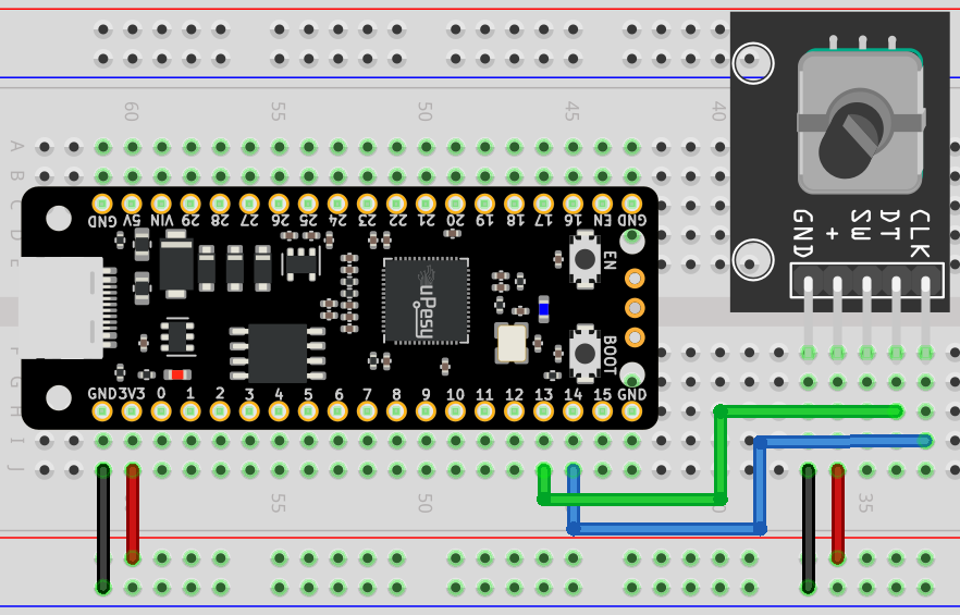
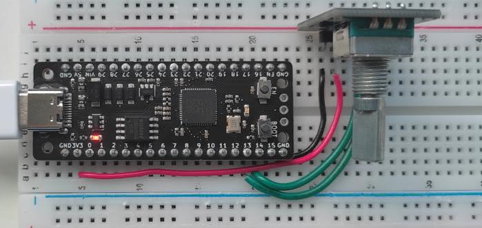
Here is a suggestion for how to connect the Raspberry Pi Pico to the uPesy RP2040 DevKit board:
Rotary Encoder |
Raspberry Pi Pico |
|---|---|
|
|
|
|
|
Not used here |
|
|
|
|
The scheme to be done is as follows:
Note
I suggest supplying the encoder with 3.3V to ensure that the logic levels meet the Pi Pico specifications.
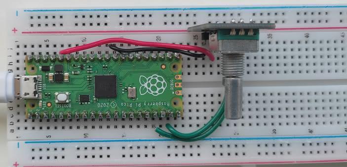
And here is an example of breadboard assembly:
Get the angular position of the KY-040 rotary encoder
An incremental encoder does not give us the angle in degrees. Instead, it provides us with the number of increments made. We need to use our programming skills to find the angle in our particular case. All we need is the value of the increment.
Various techniques can be used to determine the encoder increment. The most advantageous method detects the steps without interfering with the program’s operation instead of a “naive” strategy that continuously checks the logic signals received from the encoder. This ensures that the Pico considers all steps when the encoder is spun rapidly.
Note
Hardware interrupts can be used to detect logical level changes. These are not connected to the CPU, so the loop() function can be used for other tasks.
Unfortunately, there isn’t yet a library optimized for the Raspberry Pi Pico and written in Arduino code. On the other hand, there are ready-made codes written in C that can be used with the Pico SDK.
The Pico’s classic interrupts and PIO (Parallel Input/Output) pins can be used by libraries. This allows us to link a basic assembly code to the hardware blocks of the PIO , thus delegating the counter logic. This makes it easier to use.
You can use this library with the Arduino IDE if you’re starting. However, the installation is a bit different; instead of using the Arduino IDE, you’ll need to copy and paste the two files, quadrature.pio and quadrature.pio.h into your project folder (where the .ino file is located). These files can be found in the GitHub repository.
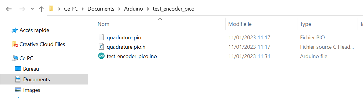
The source files are copied into your Arduino IDE project folder
And here is the basic code to retrieve the value of the increment.
#include "hardware/pio.h"
#include "quadrature.pio.h"

#define QUADRATURE_A_PIN 13
#define QUADRATURE_B_PIN 14

PIO pio = pio0;
uint offset, sm;

void setup() {
  Serial.begin(115200);
  offset = pio_add_program(pio, &quadrature_program);
  sm = pio_claim_unused_sm(pio, true);
  quadrature_program_init(pio, sm, offset, QUADRATURE_A_PIN, QUADRATURE_B_PIN);
}

void loop() {
  pio_sm_exec_wait_blocking(pio, sm, pio_encode_in(pio_x, 32));
  uint encoder_value = pio_sm_get_blocking(pio, sm);
  Serial.println(encoder_value);
  delay(200);
}
Here we use the pio0 . To get the value of the increment, we need to use the 2 functions pio_sm_exec_wait_blocking() and pio_sm_get_blocking() .
Note
Counting is done in the background via PIO. The increment value is retrieved only when required.
Detecting the pressure of the push button
The library doesn’t provide any push button detection. However, it’s possible to add a push button to an Arduino project and program it. You can set up an interrupt to detect the button behind the scenes.
List of libraries for a rotary encoder
If you’re just getting started, there are several libraries to consider for your project. Look at the GitHub repositories to see which is right for you. 😊
This section is available to premium members only. You still have 3% to discover.
Subscribe for only 5$/monthAlready subscribed? Sign in