Using a servo motor with an ESP32 board in MicroPython
(Updated at 01/06/2023)
Servo motors, frequently shortened to “servo”, are a special form of motor that can be fixed to a specific position with great precision. This position is maintained until a new instruction is given.
They have an excellent power-to-weight ratio. TowerPro’s popular SG90 blue servo has a torque of 1.5 kg/cm for only 9g. Its low price and ease of control from an ESP32 make it a popular choice for makers!
Note
Servos are widely used in model making (wheel steering in remote controlled cars, control of rudder and elevator on airplanes, etc.), but also in robotics and industry, for example to regulate liquid flows in valves.
Getting to grips with the SG90 actuator
The main difference between a servo motor and a conventional motor is that most servo motors can only rotate between 0 and + 180 degrees. A servomotor consists of a conventional DC motor, various gears to increase torque (and reduce speed) and the servo system. The feat is to have managed to pack all this mechanism in such a small box!
Warning
The plastic stop on the actuator that limits rotation is relatively fragile. It is important to avoid turning the actuator shaft by hand and forcing it to the stop.
Operation of a servomotor
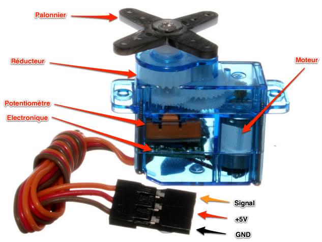
A small DC motor is connected to a potentiometer via an electronic circuit, which allows the speed of the motor to be finely regulated according to the position of the potentiometer. A series of gears is attached to the motor’s output shaft to multiply the torque while reducing its speed. When the motor turns, the gears drive the movement of the arm which in turn drives the potentiometer. If the movement stops, the electronic circuit continuously adjusts the motor speed to keep the potentiometer and therefore the arm at the same position. This feature is particularly useful for robot arms that do not fall back under their own weight when the movement stops.
Note
It’s kind of like an intelligent engine 🙂
This small servomotor is controlled using a pulse width modulated (PWM) signal with a frequency of 50 Hz, i.e. one pulse every 20ms. The position of the actuator is determined by the duration of the pulses, usually varying between 1ms and 2ms.
How to power the actuator with an ESP32
In the SG90 servo data sheet the optimal power supply is 5V. However, it seems to work also with 3.3V.
Note
With a voltage of 5V, the rotation will be slightly faster!
A servo motor consumes a lot of current, especially when it exerts a lot of torque. Since the 5V pin on most ESP32 boards comes directly from the USB bus, you will be limited to a maximum of 500mA. With 1 or 2 servo motors connected the ESP32 should hold the load.
Beyond 2, use a separate power supply instead. In this case, be sure to connect a pin GND from the board to the negative terminal of the actuator power supply 😉.
Warning
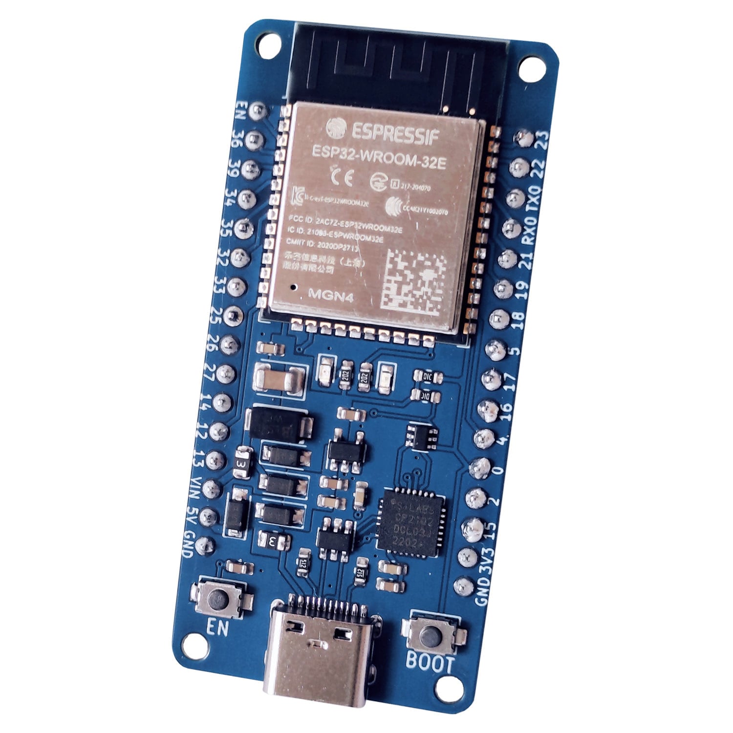
On uPesy ESP32 boards, the self-resetting fuse may trip if the current is too high.
SG90 actuator connections to the uPesy ESP32
An SG90 servo motor contains 3 wires: 2 for the power supply and 1 for the PWM control signal. The colors of the wires allow to differentiate them:
Servomoteur SG90 |
Couleur du fil |
ESP32 |
|---|---|---|
|
Marron |
|
|
Rouge |
|
Signal |
Orange |
|
Note
On some servo motor models, the signal wire color is yellow or white instead of orange.
Any output pin of the ESP32 can be used to control the servo motor because the ESP32 pins are all capable of producing a PWM output.
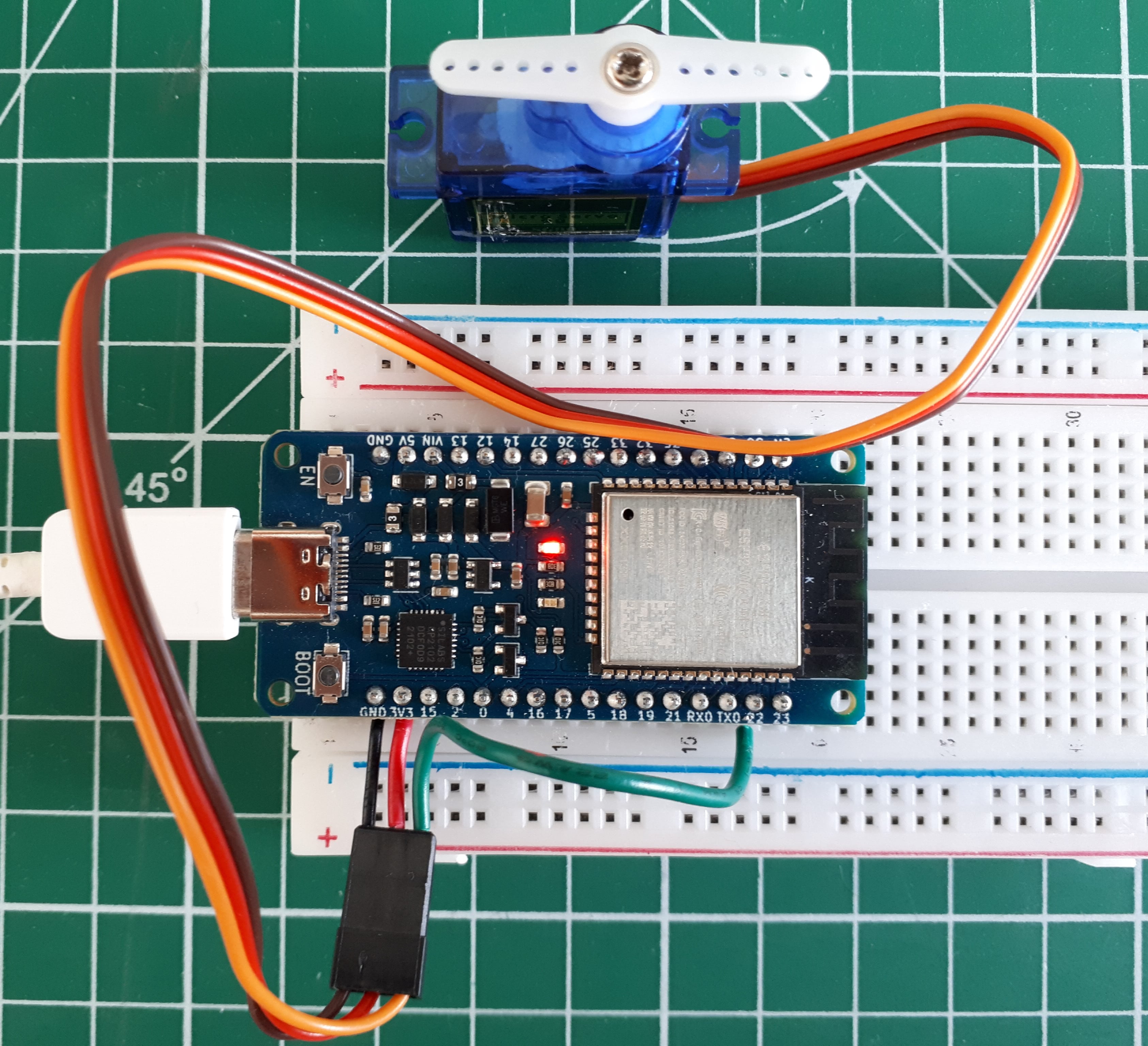
Circuit for driving a servomotor with an ESP32
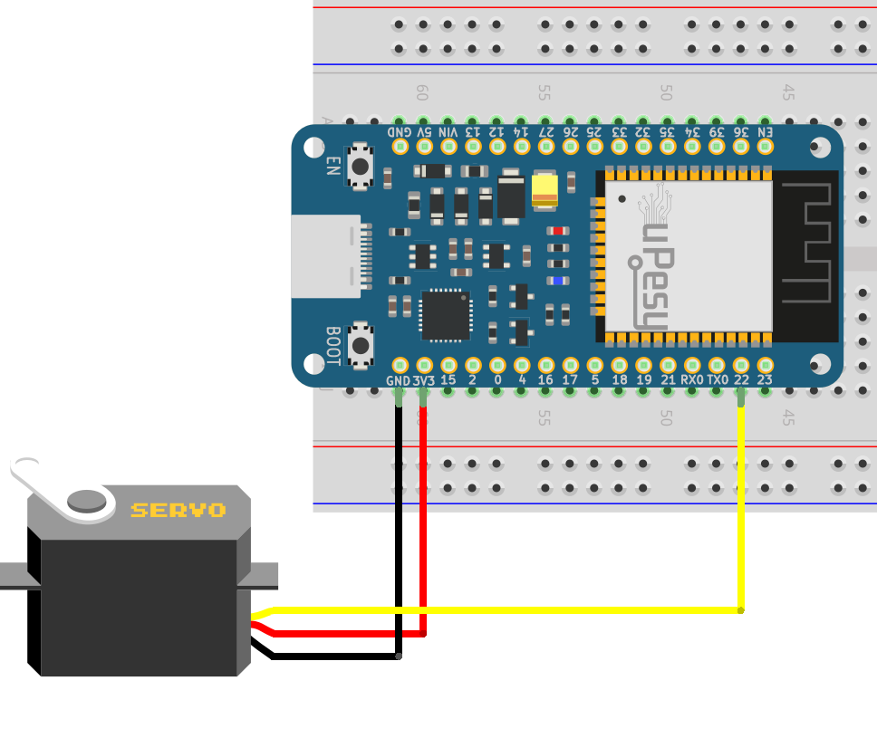
Control a servo motor from the ESP32 with a Python script
In fact, since it is the pulse width of the PWM signal that tells the servo motor the desired angular position, there is no real need for a library to master the beast 😎. But it can quickly become tedious to calculate the right values, especially when you want to drive several at the same time. That’s why I’ll recommend using a ready-made library instead to simplify your life in our future DIY projects.
Basic Python script to drive the servo with its own calculations
With the SG90 servo from TowerPro, the minimum position corresponds to a pulse width of 0.5ms and the maximum position to one of 2.4ms. By doing some calculations, we can deduce the duty-cycle of the PWM, then the value in bits of the pulse width. I will not detail the calculations, because we will rather use a ready-made library for the continuation.
Note
The difficulty is to find the right PWM pulse width to obtain a given angular position.
Here is a basic script:
from machine import Pin,PWM
import time

sg90 = PWM(Pin(22, mode=Pin.OUT))
sg90.freq(50)

# 0.5ms/20ms = 0.025 = 2.5% duty cycle
# 2.4ms/20ms = 0.12 = 12% duty cycle

# 0.025*1024=25.6
# 0.12*1024=122.88

while True:
    sg90.duty(26)
    time.sleep(1)
    sg90.duty(123)
    time.sleep(1)
I grant you that it is not very easy to understand. That’s why we are going to use a library!
Control a servo via a Python script with the library servo.py
I suggest you to use this following MicroPython library to easily control the servo motor. It is installed like other MicroPython libraries: copy and paste the file on your ESP32 board in the MicroPython file manager.
Warning
In the current version of MicroPython for the ESP32 (v1.19), this library is not present as standard. Only the Pyboard board has a library servo included as standard in MicroPython.
from machine import Pin, PWM

class Servo:
    # these defaults work for the standard TowerPro SG90
    __servo_pwm_freq = 50
    __min_u10_duty = 26 - 0 # offset for correction
    __max_u10_duty = 123- 0  # offset for correction
    min_angle = 0
    max_angle = 180
    current_angle = 0.001


    def __init__(self, pin):
        self.__initialise(pin)


    def update_settings(self, servo_pwm_freq, min_u10_duty, max_u10_duty, min_angle, max_angle, pin):
        self.__servo_pwm_freq = servo_pwm_freq
        self.__min_u10_duty = min_u10_duty
        self.__max_u10_duty = max_u10_duty
        self.min_angle = min_angle
        self.max_angle = max_angle
        self.__initialise(pin)


    def move(self, angle):
        # round to 2 decimal places, so we have a chance of reducing unwanted servo adjustments
        angle = round(angle, 2)
        # do we need to move?
        if angle == self.current_angle:
            return
        self.current_angle = angle
        # calculate the new duty cycle and move the motor
        duty_u10 = self.__angle_to_u10_duty(angle)
        self.__motor.duty(duty_u10)

    def __angle_to_u10_duty(self, angle):
        return int((angle - self.min_angle) * self.__angle_conversion_factor) + self.__min_u10_duty


    def __initialise(self, pin):
        self.current_angle = -0.001
        self.__angle_conversion_factor = (self.__max_u10_duty - self.__min_u10_duty) / (self.max_angle - self.min_angle)
        self.__motor = PWM(Pin(pin))
        self.__motor.freq(self.__servo_pwm_freq)
Warning
The code of this library works only for ESP32 boards (the code is slightly different for the Raspberry Pi Pico for example)
To use the library, it is very simple. After importing the class Servo object, we define a Servo which represents our blue servomotor. We specify the pin used to drive it in the manufacturer’s parameters.
Then we indicate the desired angular position with the function .move(angle) .
from servo import Servo
import time

motor=Servo(pin=22) # A changer selon la broche utilisée
motor.move(0) # tourne le servo à 0°
time.sleep(0.3)
motor.move(90) # tourne le servo à 90°
time.sleep(0.3)
motor.move(180) # tourne le servo à 180°
time.sleep(0.3)
motor.move(90) # tourne le servo à 90°
time.sleep(0.3)
motor.move(0) # tourne le servo à 0°
time.sleep(0.3)
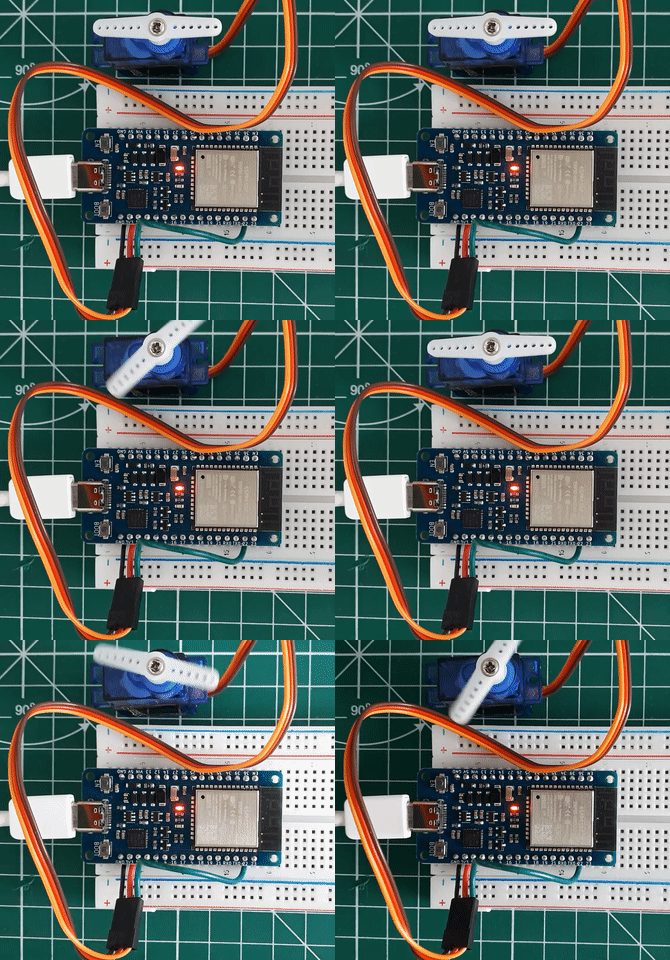
Here is a demonstration video with the above code:
