Measure analog voltage on ESP32 with ADC
(Updated at 11/28/2022)
As its name suggests, the ADC (Analog to Digital Converter) allows it to convert an analog voltage into a binary value.
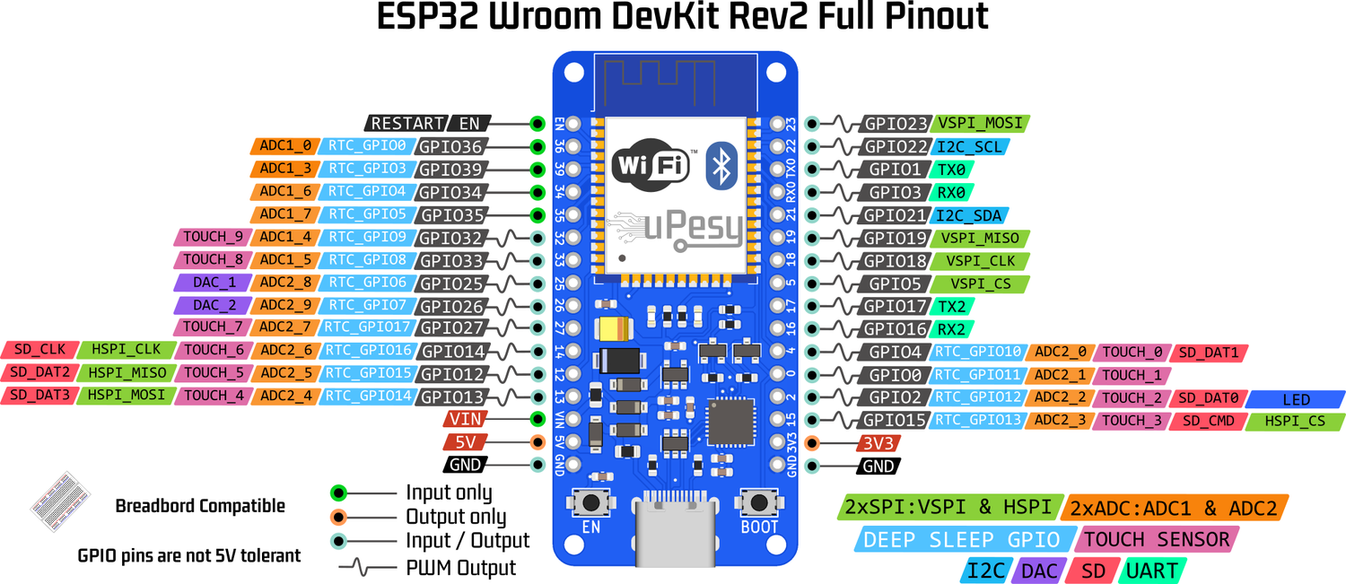
There are 2x12 bits ADCs on the ESP32, the ADC1 with 8 channels and the ADC2 with 10 channels. Each channel of the ADC allows measuring a pin.
ADC limitation on the ESP32
The ADC is not a strong point of the ESP32 because it has many flaws. Use the Arduino one or an external ADC if you want to make accurate measurements.
Warning
Although it sounds strange, the Arduino’s 10-bit ADC (1024 values) is more accurate and reliable than the ESP32’s 12-bit (4096 values).
The ADC of the ESP32 has several flaws:
ADC2 cannot be used with enabled WiFi since it is used internally by the WiFi driver. Since there is a good chance of using WiFi on a microcontroller designed to use it, only the ADC1 and its 8 channels can be used.
The ADC can only measure a voltage between 0 and 3.3V. You cannot directly measure analog voltages between 0 and 5V.
Non-linearity
The ADC of the ESP32 is not very linear (the ADC response curve is not a linear line), especially at the ends of its operating range (around 0V and 3.3V)
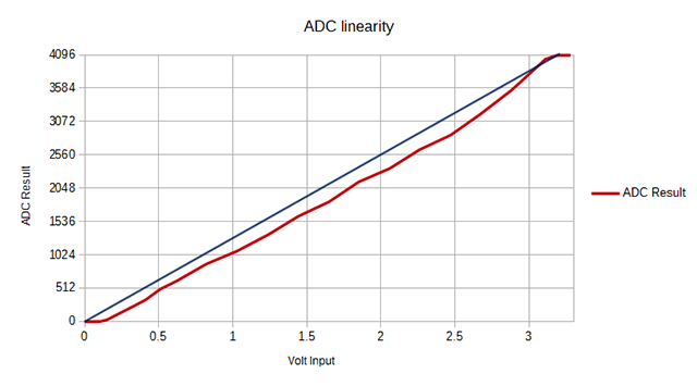
Basically, this means that the ESP32 cannot distinguish a signal of 3.2V and 3.3V: the measured value will be the same (4095). Likewise, the ESP32 will not differentiate between a 0V and 0.2V signal for small voltages.
Note
It is possible to calibrate the ADC to reduce this linearity flaw. An example is available here .
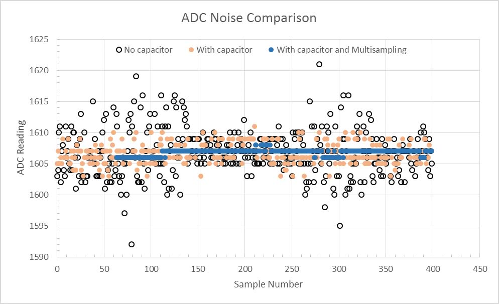
The electrical noise of the ADC implies a slight fluctuation of the measurements:
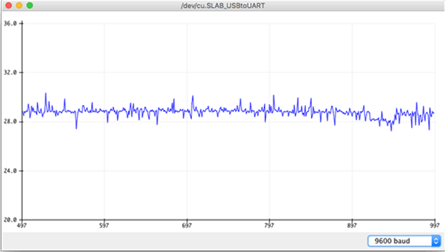
Here too, it is possible to try to “correct” this defect by adding a capacitor at the output and with oversampling :
Usage
The primary use of the ESP32 ADC is the same as on the Arduino with the function analogRead() .
To read the voltage of the VP pin (GPIO36) of the ESP32:
pinMode(36, INPUT); //It is necessary to declare the input pin
analogRead(36);
Note
There are also more advanced functions.
To change the ADC resolution:
analogReadResolution(resolution) // Resolution between 9-12 bits
Mini-Project
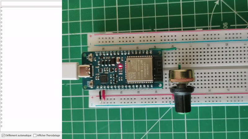
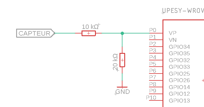
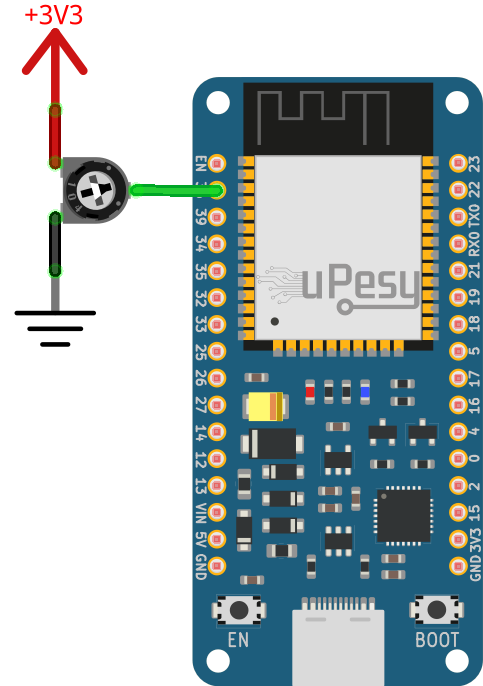
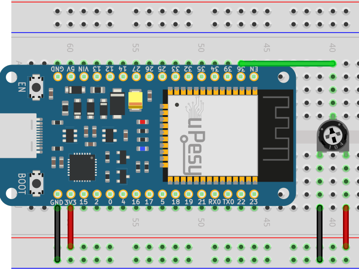
We will test the ADC using a potentiometer (variable resistor).
Electrical schematic for the potentiometer
Code for reading potentiometer values
Solution
// The potentiometer is connected to GPIO36 (Pin VP)
const int potPin = 36;

// Potentiometer value
int potValue = 0;

void setup() {
Serial.begin(115200);
delay(1000);
pinMode(potPin,INPUT_PULLUP);
}

void loop() {
// Measures the value of the potentiometer
potValue = analogRead(potPin);
Serial.println(potValue);
delay(250);
}
Final results
When you turn the potentiometer, you get :